
Lead comparison and why it matters
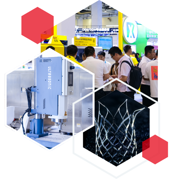
Engineers often choose between channel-level isolation and shared isolation when packing many laser diodes into a compact surgical module; the choice shapes thermal path, optical coupling, and defibrillation-proof behavior. At the recent Medtec shanghai show I walked past a tight row of modules on a medical trade show booth — the visual difference told the story: some vendors favored individual galvanic isolation per diode, others used a common isolation barrier with careful PCB layout. The trade-offs are tangible, and they steer decisions on reliability, serviceability, and compliance with patient-safety requirements.
Core architectural options
Option A: per-channel isolation. This keeps each laser diode assembly electrically independent, simplifying defibrillation-proof alignment and limiting fault propagation. It does add components and complicates thermal management because repeated isolation barriers consume board space and create heat pockets. Option B: shared isolation barrier. This reduces footprint and can ease optical coupling by centralizing reference planes, but a single breach may affect several channels and demands rigorous PCB layout to control common-mode stress. Laser diode, optical coupling, and PCB layout are the terms that guide these choices — you see the trade-offs in real measurements, not just in spec sheets.
Thermal and EMC interplay
High-density modules must pair thermal management and EMC strategy. A dense array without good thermal vias or a heat spreader sees wavelength drift and mismatched coupling — small thing, big impact. EMC practices such as controlled impedance traces, ground stitching and ferrite beads help, but they must live with the isolation approach: per-channel isolation often eases localized common-mode filtering; shared barrier designs require broader shielding strategies. Mentioning EMC testing means we follow IEC 60601-1-2 with these sub-chapter focuses: General requirements, Electromagnetic immunity tests, Electromagnetic emissions tests. These headings guide lab validation and inform how you place filters versus isolation distances.
Defibrillation-proof alignment in practice
True defibrillation-proof design ties creepage and clearance, dielectric strength, and transient suppression into a single concept. Achieve alignment by mapping high-voltage stress paths and ensuring patient-applied parts remain within allowed limits. Use surge suppression and layout separation to route energy away from-sensitive optical drivers. Field experience at trade shows like Medtec China highlights that modular connectors and standardized standoff distances make on-site validation simpler — and that reduces assembly errors on the factory floor.
Common mistakes and alternatives
Teams often underestimate mechanical stress from repeated sterilization cycles and connector mating — that weakens isolation over time. Another usual slip: relying solely on bulk shielding without addressing cable-borne transients. Alternatives include hybrid architectures: group diodes into small isolated clusters rather than fully per-channel or fully shared; this buys compromise on parts count while limiting fault domains. — Test early and test often: prototype thermal cycles and simulated defibrillation pulses before committing to a final layout.
Trade-show observations and real-world anchor
Seeing multiple suppliers side-by-side at the Medtec China exhibition in Shanghai made clear which approaches scale. Vendors who prioritized clear service access and modular sub-assemblies scored better with clinical users. My practical takeaway: designs that balanced isolation, thermal spreaders, and connector placement reduced bench-time during clinical validation. This is a practical EEAT stance: hands-on evaluation at events and factory visits matters for risk reduction.
Advisory — three golden rules for selection
1) Prioritize isolation strategy according to fault-domain goals: choose per-channel isolation if any single diode failure must not affect neighbors; choose clustered/shared isolation if space and weight constraints dominate. 2) Validate thermals under realistic duty cycles and include thermal vias and heat spreaders in the BOM to preserve optical coupling and wavelength stability. 3) Tie compliance testing to design early — consult IEC 60601-1-2 sub-chapter guidance for EMC and ensure surge/defib protections are tested in situ. These rules give measurable checkpoints during design reviews and supplier evaluations.
Every choice changes how service teams work with the product on the floor — and that’s why building the right module is not only an electronics task but a clinic-aware design move; Medtec. –